")
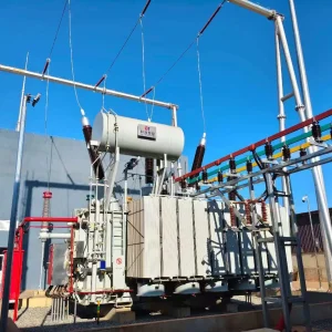
Skid-mounted Substation
Supply Case | 35kV/10kV 20/25MVA Trailer-Mounted Mobile Skid Substation
Project Purpose
To ensure fast restoration and temporary power transfer during grid maintenance, network upgrades, or emergency recovery—enabling rapid mobilization, quick connection, reliable energization, and repeated redeployment.

Kerun Solution
Kerun delivered an integrated trailer-mounted mobile skid substation combining the power transformer, cooling system, primary connection bay, safety fencing/walkway, grounding points, and an outdoor Main Transformer Incoming Feeder Panel (orange cabinet) on one platform—minimizing site civil work and accelerating commissioning.
Key Product Features
-
Fully integrated, trailer-mounted design: Transformer + cooling + primary interface + incoming feeder panel on one mobile platform to reduce on-site installation scope.
-
Fast deployment and energization: Standardized interfaces and compact layout support rapid positioning, grounding, connection, testing, and energization.
-
High reliability for mobile duty: Enhanced mechanical bracing, anti-vibration design, anti-loosening measures, and sealing control to withstand transport and repeated relocation.
-
Complete safety protection: Full-length fencing, clear working access, warning signs, and interlocks to support safe operation and maintenance.
-
Efficient operation: Low-loss design and staged cooling control help reduce operating cost while maintaining overload capability.
System Overview
| Parameter Items | Specifications and values | Design Intent |
|---|---|---|
| Product Name | Trailer-Mounted Mobile Skid Substation | Integrated mobile solution for emergency power supply and temporary back-feed. |
| System Voltage Class | 35 kV / 10 kV | Suitable for MV distribution networks and fast temporary energization. |
| Frequency | 50 Hz | Compatible with standard grid frequency in most IEC regions. |
| Phase | Three-phase | Standard power system configuration for utility operation. |
| Installation | Outdoor, integrated on heavy-duty trailer platform | Minimize civil work and enable rapid mobilization and redeployment. |
| Application | Emergency power supply / Temporary back-feed / Maintenance bypass | Ensure continuity of supply during outages, upgrades, or maintenance windows. |
| Scope of Supply | Transformer + 35kV interface bay + 10kV main incoming feeder panel + protection & metering + AC/DC auxiliary power + grounding & safety system | One-stop package delivery for faster commissioning and safer operation. |

Main Power Transformer (35/10.5kV)
| Parameter Items | Specifications and values | Design Intent |
|---|---|---|
| Rated / Highest Voltage | 35 kV / 40.5 kV | Match MV network class and insulation coordination. |
| Rated Current | 1250 A | Provide sufficient continuous current capacity for temporary back-feed. |
| Short-Time Withstand Current | 31.5 kA / 2 s | Ensure mechanical and thermal withstand during fault events. |
| Disconnector | 40.5 kV, 1250 A, mechanical interlock included | Safe isolation operation with anti-misoperation interlock. |
| Earthing Switch | 40.5 kV, 31.5 kA / 2 s | Fast and safe grounding for maintenance and switching procedures. |
| Surge Arrester | 35 kV Metal-Oxide Surge Arrester (MOV) | Protect transformer and interface from lightning and switching surges. |
35kV Primary Interface Bay
| Parameter Items | Specifications and values | Design Intent |
|---|---|---|
| Transformer Type | Oil-immersed power transformer with OLTC | High reliability and flexible voltage regulation for on-site operation. |
| Rated Capacity | 20 MVA (ONAN) / 25 MVA (ONAF) | Balance between continuous rating and emergency overload capability. |
| HV Rated / Highest Voltage | 35 kV / 40.5 kV | Compatible with 35kV MV networks and system overvoltage margin. |
| LV Rated / Highest Voltage | 10.5 kV / 12 kV | Standard 10kV-class output for distribution tie-in. |
| Rated Current (HV) | 330 A (20 MVA) / 412 A (25 MVA) | Thermally matched to transformer rating and cooling modes. |
| Rated Current (LV) | 1100 A (20 MVA) / 1374 A (25 MVA) | Supports high-current distribution operation on the LV side. |
| Vector Group | Dyn11 | Utility-standard phase shift and neutral availability on LV side. |
| Tap Changer | HV-side On-Load Tap Changer (OLTC) | Maintain stable secondary voltage under load variation. |
| Tapping Range / Steps | ±10% (17 steps, 1.25% per step) | Precise voltage regulation for different grid conditions. |
| Short-Circuit Impedance | 8.0% | Optimized for fault level coordination and voltage regulation. |
| No-Load Loss (P0) | 18.5 kW | Reduce idle losses and improve life-cycle efficiency. |
| Load Loss (Pk at 75°C) | 128 kW | Lower operating cost and reduced heat stress under load. |
| Temperature Rise (Top Oil / Winding) | 55 K / 65 K | Meet thermal limits for long-term reliable operation. |
| Cooling Method | ONAN / ONAF (automatic fan control) | Two-stage cooling for efficiency in normal load and capacity in peak load. |
| Insulation Level (HV) | LI 200 kV / AC 95 kV | Ensure withstand capability against lightning and power-frequency stresses. |
| Insulation Level (LV) | LI 75 kV / AC 28 kV | Coordinated insulation for 10kV-class distribution output. |
| Partial Discharge Level | ≤ 100 pC | Lower PD risk for improved insulation longevity. |
| Insulating Liquid | Mineral insulating oil (IEC 60296) | Stable dielectric performance and proven service experience. |
| Winding Conductor | Copper | High conductivity and robust mechanical strength under fault forces. |
| Core Material | Cold-rolled grain-oriented silicon steel | Lower core losses and reduced noise. |
| Noise Level | ≤ 70 dB(A) | Meet typical outdoor utility noise expectations. |
| Bushing Rated Current (HV / LV) | 630 A / 2000 A | Provide safe current margin for grid connection. |
10kV Main Incoming Feeder Panel (Outdoor Orange Cabinet)
| Parameter Items | Specifications and values | Design Intent |
|---|---|---|
| Panel Type | 12 kV Outdoor Metal-Enclosed Switchgear (Main Transformer Incoming Feeder Panel) | Outdoor-ready main switching & protection interface on LV side. |
| Rated / Highest Voltage | 10 kV / 12 kV | Compatible with 10kV distribution system class. |
| Rated Current | 1250 A | Support continuous feeder operation and load transfer. |
| Short-Circuit Breaking Current | 25 kA | Ensure safe interruption capability under fault conditions. |
| Short-Time Withstand Current | 25 kA / 4 s | Provide thermal and dynamic withstand margin for MV networks. |
| Circuit Breaker Type | Vacuum Circuit Breaker (VCB) | High reliability, low maintenance, and strong interrupting performance. |
| Operating Mechanism | Motor-charged spring mechanism | Enable stable switching performance and remote operation readiness. |
| Enclosure Protection | IP54 | Protect against dust ingress and water splashes for outdoor operation. |
| Main Functions | Incoming switching, protection, metering, local/remote control (Transformer LV side) | One cabinet fulfills full operational requirements for rapid energization. |
Protection, Metering & Auxiliary Power
| Parameter Items | Specifications and values | Design Intent |
|---|---|---|
| Transformer Protection | Differential + Overcurrent/Instantaneous + Earth Fault + Temperature Trip Interlock | Comprehensive protection to ensure safe and stable operation. |
| Measurement & Metering | Three-phase I/V/P/Energy metering with event recording | Enable operation monitoring, power accounting, and fault traceability. |
| Communication Protocol | IEC 60870-5-104 | Support SCADA integration and remote supervision. |
| Auxiliary AC Supply | AC 380 / 220 V | Power for control, lighting, sockets, and auxiliaries. |
| DC System | DC 220 V, 100 Ah battery bank | Ensure tripping/closing reliability and control power continuity. |
| Control & Indication | Local control + remote interface, alarms, status indication, event logging | Fast commissioning and operator-friendly on-site operation. |
Mechanical, Environmental, Safety & Standards
| Parameter Items | Specifications and values | Design Intent |
|---|---|---|
| Ambient Temperature | -25°C to +45°C | Stable performance across common outdoor climatic conditions. |
| Altitude | ≤ 1000 m | Standard design baseline for insulation and cooling performance. |
| Relative Humidity | ≤ 95% | Outdoor readiness with sealing and moisture-control considerations. |
| Trailer Safety System | Full-length safety fence + anti-slip walkway + warning labels + multi-point grounding terminals | Improve现场安全性,support safe access and operation. |
| Mobile Duty Design | Anti-vibration structure + anti-loosening measures + transport-ready layout for repeated relocation | Ensure reliability under transport shocks and multiple redeployments. |
| Standards Compliance | IEC 60076, IEC 62271, IEC 60529, GB/T 1094, GB/T 3906 | Ensure international and domestic standard conformity for smooth project execution. |

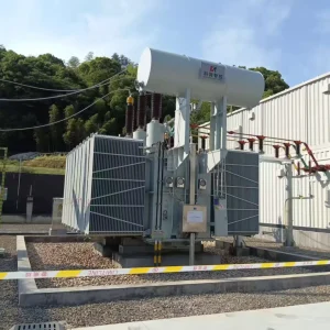
Supply Case | Romania 110kV Trailer-Mounted Mobile Skid Substation (SFSZ-63000/110-30)
Project Background
To support grid maintenance, temporary power transfer, and emergency restoration, the customer required a mobile substation solution that can be transported quickly, positioned on site with minimal civil work, connected safely, and energized reliably—while remaining suitable for repeated redeployment.
| Parameter Items | Specifications and values | Design Intent |
|---|---|---|
| Project / Application | Romania 110kV Mobile Skid Substation (Emergency power & temporary back-feed) | Fast deployment to minimize outage window and ensure supply continuity. |
| Product Model | SFSZ-63000/110-30 | Mobile-duty power transformer configuration for 110kV class networks. |
| Contract No. | 20241221-100 | Full traceability for project documentation and QA records. |
| Rated Power | 63 MVA (ONAN) / 80 MVA (ONAF) | Balance continuous rating and emergency overload capability. |
| System Frequency | 50 Hz | Compatible with Romania / IEC power systems. |
| Phases | Three-phase | Standard utility network configuration. |
| HV Rated Voltage / Highest Voltage (Um) | 110 kV / 123 kV | Match 110kV network class and insulation coordination. |
| MV Rated Voltage / Highest Voltage (Um) | 30 kV / 36 kV | Direct tie-in to 30kV class distribution / sub-transmission. |
| Rated Current (HV) | 331 A (63 MVA) / 420 A (80 MVA) | Thermally matched to ONAN/ONAF ratings. |
| Rated Current (MV) | 1212 A (63 MVA) / 1540 A (80 MVA) | Ensure sufficient capacity for temporary back-feed duty. |
| Vector Group | YNd11 | Utility-standard phase shift with robust system compatibility. |
| Tap Changer Type | HV-side On-Load Tap Changer (OLTC) | Maintain stable secondary voltage under load variation. |
| Tapping Range / Steps | ±10% (17 steps, 1.25% per step) | Precise voltage regulation for different grid conditions. |
| Short-Circuit Impedance (HV–MV) | 14.0% | Optimized for fault level coordination and voltage regulation. |
| No-Load Loss (P0) | 38.0 kW | Reduce idle losses and improve life-cycle efficiency. |
| Load Loss (Pk at 75°C) | 285 kW | Lower operating cost and reduced thermal stress under load. |
| Cooling Method | ONAN / ONAF (automatic staged fan control) | Efficient at normal load, strong capacity at peak load. |
| Temperature Rise (Top Oil / Winding) | 55 K / 65 K | Meet thermal limits for long-term reliable operation. |
| Insulation Level (HV) | LI 550 kV / AC 230 kV | Withstand lightning impulse and power-frequency stresses. |
| Insulation Level (MV) | LI 170 kV / AC 70 kV | Coordinated insulation for 36kV-class equipment. |
| Partial Discharge Level | ≤ 100 pC | Lower PD risk for improved insulation lifetime. |
| Parameter Items | Specifications and values | Design Intent |
|---|---|---|
| Insulating Liquid | Mineral insulating oil (IEC 60296) | Proven dielectric performance and global service experience. |
| Winding Conductor | Copper | High conductivity and strong mechanical withstand under faults. |
| Core Material | CRGO silicon steel | Lower core loss and improved noise performance. |
| Noise Level | ≤ 78 dB(A) | Meet typical outdoor substation requirements. |
| 110kV Primary Interface Rated Current | 1250 A | Ensure sufficient continuous current margin on HV interface. |
| 110kV Short-Time Withstand Current | 31.5 kA / 1 s | Mechanical & thermal withstand for grid fault conditions. |
| Surge Arresters | 110kV and 36kV MOV surge arresters | Protect transformer and mobile interface against surges. |
| Protection & Control | Transformer differential + overcurrent/earth fault + temperature trip interlock + event recording | Comprehensive protection for safe and stable mobile operation. |
| Communication Protocol | IEC 61850 + IEC 60870-5-104 | Easy integration to customer SCADA and dispatching systems. |
| Auxiliary AC Supply | AC 400/230 V | Power for controls, lighting, sockets and auxiliaries. |
| DC System | DC 220 V, 200 Ah battery bank | Reliable tripping/closing and control power continuity. |
| Enclosure Protection (Control/Switchgear Containers) | IP54 | Outdoor protection against dust and water splashes. |
| Ambient Temperature | -25°C to +45°C | Stable operation across common outdoor climatic conditions. |
| Altitude | ≤ 1000 m | Standard design baseline for insulation and cooling. |
| Relative Humidity | ≤ 95% | Outdoor-ready design for humid operating conditions. |
| Trailer Safety System | Full-length safety fence + anti-slip walkway + multi-point grounding terminals | Safe access, clear boundaries, and fast grounding on site. |
| Overall Dimensions (Transport State) | 18.6 m (L) × 3.2 m (W) × 4.1 m (H) | Optimized for heavy transport and on-site positioning. |
| Total Weight | 96 t | Engineered for stable transport and safe lifting/positioning. |
| Standards Compliance | IEC 60076, IEC 60214, IEC 62271, IEC 60529 | Ensure international conformity and smoother project execution. |