
What Is 480 To 240 Single Phase Transformer Wiring Diagram?
-
480 to 240 single phase transformer wiring diagram explains oil-immersed transformer wiring and safe voltage conversion.
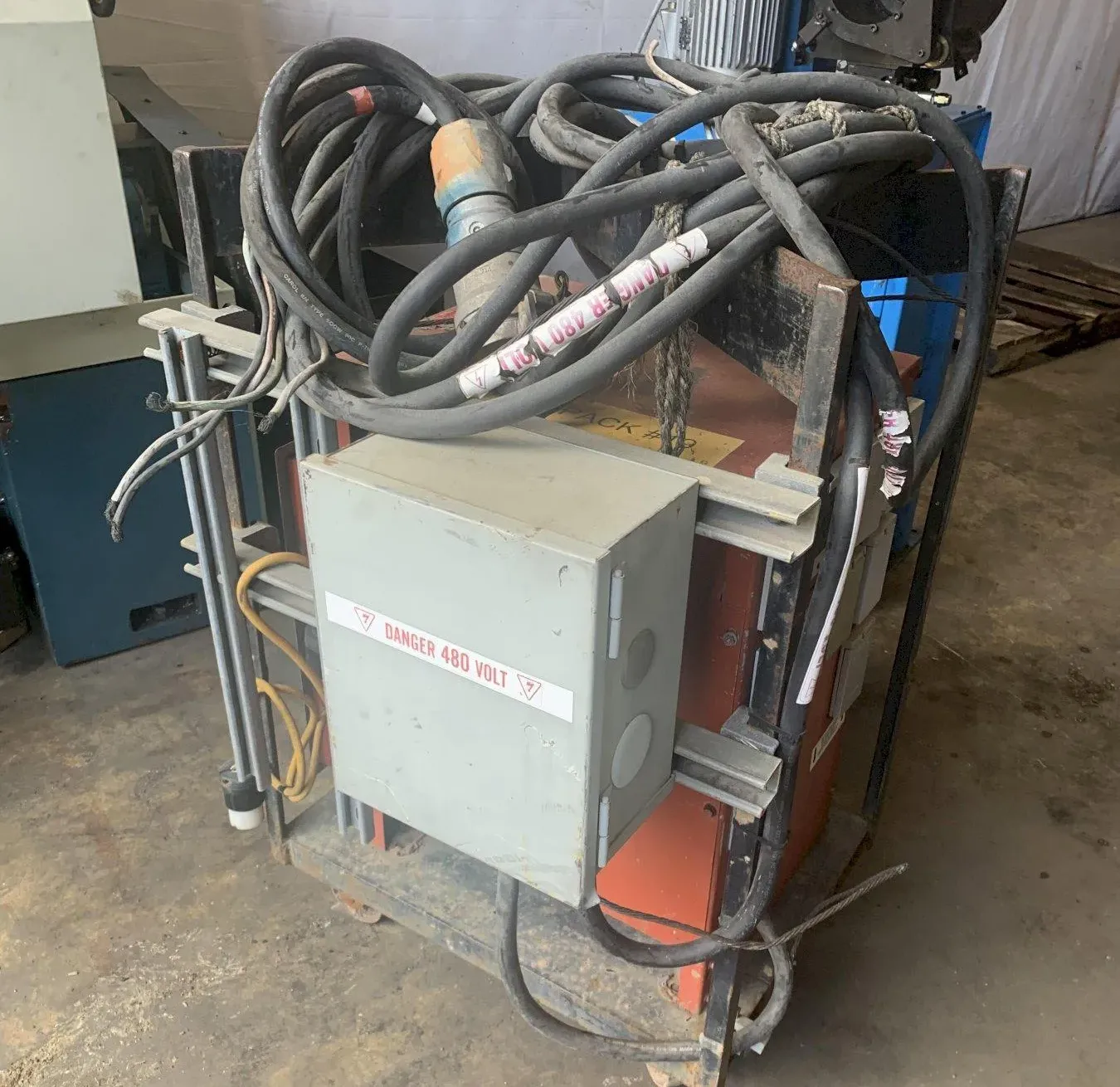
Industrial facilities depend on stable voltage conversion for reliable equipment operation. A 480 to 240 single phase transformer wiring diagram helps electricians connect oil-immersed transformers safely inside production environments. Manufacturing plants often distribute 480V power because higher voltage reduces conductor current during transmission. Many commercial devices still require 240V input for motors, pumps, heaters, and lighting systems. Proper voltage reduction protects machinery from overheating and insulation failure. Oil-immersed transformers support continuous operation under demanding electrical conditions. Mineral insulating oil dissipates heat efficiently through radiators and cooling channels. Engineers also value oil insulation because it improves dielectric strength between windings. Careful transformer wiring reduces downtime, prevents short circuits, and supports long-term electrical stability across industrial facilities with fluctuating power demands.
What Is 480 To 240 Single Phase Transformer Wiring Diagram
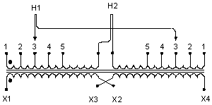
A transformer wiring diagram shows electrical connections between primary terminals, secondary terminals, grounding points, and protective devices. The 480 to 240 single phase transformer wiring diagram normally identifies H1 and H2 input terminals alongside X1 and X2 output terminals. Electricians follow these markings during installation to avoid polarity errors and unstable voltage output. Oil-immersed transformers contain copper or aluminum windings submerged inside insulating oil. Heat generated during voltage conversion transfers into the oil before reaching cooling fins or radiators. Single-phase transformers commonly support industrial control cabinets, conveyor systems, and HVAC units. Accurate diagrams also identify conductor sizing requirements and grounding methods. Proper line connections maintain voltage consistency during heavy load fluctuations. Incorrect wiring may damage motors, overload breakers, or reduce transformer service life under continuous industrial operation.
Oil-Immersed Transformer Construction And Internal Components
Oil-immersed transformers contain laminated silicon steel cores that minimize eddy current losses during electromagnetic induction. Manufacturers design windings with insulated copper conductors to improve conductivity and thermal stability. Mineral oil surrounds internal components and removes heat generated during voltage transformation. Cooling radiators increase surface area and improve heat dissipation efficiency during continuous operation. Conservator tanks manage oil expansion caused by rising temperatures inside the transformer enclosure. Bushings provide insulated conductor entry points between external wiring and internal windings. Pressure relief valves protect tanks from excessive internal pressure during electrical faults. Industrial facilities often select sealed oil systems because they reduce moisture contamination risks. Some heavy-duty applications use a 66 kV Oil-Immersed Power Transformer for large-scale distribution systems requiring stable voltage transfer under high electrical loads.
Primary And Secondary Wiring Connection Principles
Electricians connect the primary winding to the 480V supply and connect the secondary winding to 240V equipment loads. Primary terminals normally use H1 and H2 labels, while secondary terminals use X1 and X2 markings. Correct polarity alignment prevents unstable voltage output and abnormal current flow. Grounding conductors connect transformer enclosures directly to facility grounding systems for personnel safety. Oil-immersed transformers require secure cable terminations because loose conductors increase resistance and operating temperature. Many industrial panels include fused disconnects before transformer inputs for overload protection. Technicians verify voltage levels with calibrated multimeters before energizing circuits. Secondary conductors should match expected current ratings and insulation requirements. Careful torque application during terminal tightening reduces overheating risks during prolonged equipment operation inside demanding manufacturing environments.
480 To 240 Single Phase Transformer Wiring Diagram For Industrial Equipment
Industrial facilities use oil-immersed transformers across many production processes requiring dependable voltage conversion. CNC machines often require stable 240V power for servo drives and precision controllers. HVAC systems use transformed voltage for compressors, blower motors, and control circuits. Conveyor systems also depend on balanced voltage output to maintain motor efficiency during continuous production cycles. Many industrial lighting systems operate with dedicated step-down transformers for improved operational stability. Food processing plants frequently use oil-immersed transformers because they support long operating cycles with reliable thermal management. Some medium-voltage facilities integrate a 35 kV oil-immersed Transformer within larger distribution systems supplying manufacturing workshops and commercial production zones. Reliable wiring practices reduce voltage drops, limit electrical noise, and improve equipment lifespan throughout industrial operations.
Typical Transformer Voltage And Performance Characteristics
| Parameter | Typical Value | Industrial Purpose |
|---|---|---|
| Primary Voltage | 480V | Main industrial power input |
| Secondary Voltage | 240V | Equipment operating voltage |
| Frequency | 60 Hz | North American power systems |
| Cooling Method | Oil-immersed | Thermal stability improvement |
| Insulation Class | Class A or Class OA | Electrical insulation protection |
| Efficiency Range | 96%–99% | Reduced power losses |
Oil-immersed transformers achieve high operating efficiency because insulating oil removes internal heat effectively. Stable thermal management supports consistent voltage regulation during fluctuating industrial loads. Higher efficiency reduces energy waste and lowers operating costs across commercial facilities. Electrical engineers also evaluate impedance values because impedance affects fault current behavior and voltage regulation. Proper conductor sizing further minimizes voltage drops between transformers and connected equipment. Many installations use copper conductors because copper provides strong conductivity and lower resistance under heavy electrical demand. Reliable performance characteristics improve equipment protection, support long operating cycles, and reduce maintenance frequency inside industrial electrical systems.
Common Wiring Configurations Used In Industrial Facilities
Several wiring configurations support different industrial voltage requirements and operational conditions. Isolation transformers separate primary circuits from secondary equipment to reduce electrical interference and transient voltage spikes. Buck-boost transformers adjust voltage slightly when facilities experience unstable supply conditions. Center-tapped secondary systems provide dual-voltage outputs for mixed industrial equipment requirements. Some applications use grounded secondary configurations for improved personnel safety and fault detection. Oil-immersed transformers perform well in outdoor installations because insulating oil improves dielectric performance under humid conditions. Industrial facilities often install protective relays and surge arresters alongside transformers to improve system reliability. Engineers also evaluate harmonic distortion when connecting variable frequency drives. Correct wiring configuration selection supports operational efficiency, voltage stability, and long-term electrical protection within demanding manufacturing environments.
Important Safety Procedures Before Transformer Installation
Electrical safety procedures protect personnel and equipment during transformer installation activities. Technicians first perform lockout and tagout procedures before touching energized conductors. Voltage testers confirm complete circuit isolation before wiring begins. Oil-immersed transformers require grounding verification to prevent dangerous fault currents during abnormal operating conditions. Electricians inspect conductor insulation for cracks, moisture damage, or excessive wear before installation. National Electrical Code compliance remains essential for conductor sizing, overcurrent protection, and grounding practices. Industrial facilities also inspect oil levels before energizing transformers because low oil volume reduces cooling performance. Infrared thermal inspections help identify loose terminals and abnormal heating patterns after startup. Careful installation procedures minimize equipment failure risks and improve long-term operational reliability inside commercial electrical systems.
Transformer Installation Inspection Checklist
| Inspection Item | Purpose | Recommended Action |
|---|---|---|
| Oil Level Verification | Ensure cooling performance | Inspect sight glass before startup |
| Terminal Torque Check | Prevent overheating | Use calibrated torque tools |
| Grounding Continuity | Improve personnel safety | Measure grounding resistance |
| Insulation Inspection | Avoid electrical leakage | Inspect conductor jackets carefully |
| Voltage Testing | Verify output stability | Measure energized secondary voltage |
| Thermal Monitoring | Identify abnormal heating | Perform infrared inspections |
Careful inspection procedures reduce startup failures and improve transformer operating reliability. Industrial electricians often document inspection results for maintenance tracking and regulatory compliance purposes. Thermal monitoring remains important because excessive heat accelerates insulation aging inside oil-immersed transformers. Grounding continuity testing also protects sensitive equipment from transient fault currents. Facilities operating continuous production lines normally perform scheduled inspections to prevent unplanned downtime. Voltage verification confirms stable secondary output before sensitive machinery becomes energized. Maintenance teams also inspect radiator surfaces for dirt accumulation because blocked airflow reduces cooling efficiency. Consistent inspection routines support longer transformer service life and improve operational safety within demanding industrial environments.
Frequent Wiring Mistakes That Cause Equipment Failure
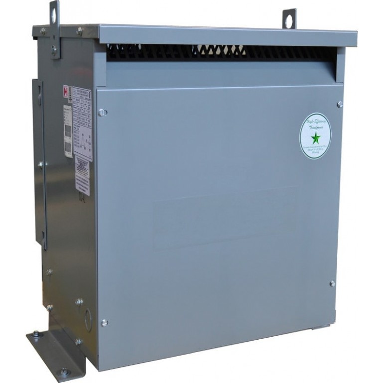
Improper transformer wiring frequently causes overheating, unstable voltage output, and unexpected equipment shutdowns. A 480 to 240 single phase transformer wiring diagram helps technicians verify correct terminal arrangements before installation begins. Incorrect terminal pairing remains one of the most common installation mistakes within industrial facilities. Reversed polarity may damage motors, relays, and electronic controllers during startup. Undersized conductors create excessive resistance and increase cable operating temperatures. Loose terminal connections also generate heat buildup and accelerate insulation deterioration. Some facilities neglect grounding verification, which increases shock hazards and fault current risks. Overloaded transformers often experience oil temperature increases that reduce insulation lifespan. Electricians should always compare wiring layouts with manufacturer schematics before energizing equipment. Careful installation practices reduce maintenance costs, improve electrical stability, and protect commercial equipment from severe operational failures caused by preventable wiring mistakes.
Best Practices For Reading Industrial Wiring Diagrams
Accurate diagram interpretation improves installation efficiency and reduces electrical troubleshooting time. Electricians first identify transformer ratings, terminal labels, and conductor paths before beginning any connection work. Line diagrams usually display primary voltage inputs on the left side and secondary outputs on the right side. Grounding symbols identify enclosure bonding points and fault protection connections. Dashed lines sometimes indicate optional control devices or protective equipment configurations. Technicians also review conductor ampacity charts before selecting installation cables. Voltage testing after installation confirms proper transformer operation under energized conditions. Industrial facilities frequently maintain updated schematic documentation because outdated diagrams increase installation risks. Proper diagram interpretation supports safe electrical practices and improves reliability across industrial power distribution systems using oil-immersed transformers.
Key Steps Electricians Follow During Transformer Wiring
Professional electricians normally follow structured installation procedures to reduce operational risks and improve system stability.
- Inspect transformer oil levels and enclosure condition
- Verify primary and secondary voltage ratings
- Confirm conductor insulation classifications
- Tighten terminals using calibrated torque tools
- Test grounding continuity before energizing circuits
- Measure secondary voltage after startup
- Monitor operating temperature during initial load conditions
- Record installation data for maintenance documentation
Structured installation procedures improve transformer reliability and reduce unexpected equipment downtime. Industrial maintenance teams frequently review torque values because vibration may loosen terminals over time. Voltage testing also confirms balanced output under varying electrical loads. Many facilities perform thermal imaging inspections after transformer startup to identify abnormal heating patterns around conductors and terminals. Oil quality monitoring remains important because contaminated insulating oil reduces dielectric performance and cooling efficiency. Preventive maintenance programs support longer service life while reducing emergency repair expenses across industrial electrical systems operating under continuous production demands.
FAQ
What makes oil-immersed transformers suitable for industrial environments?
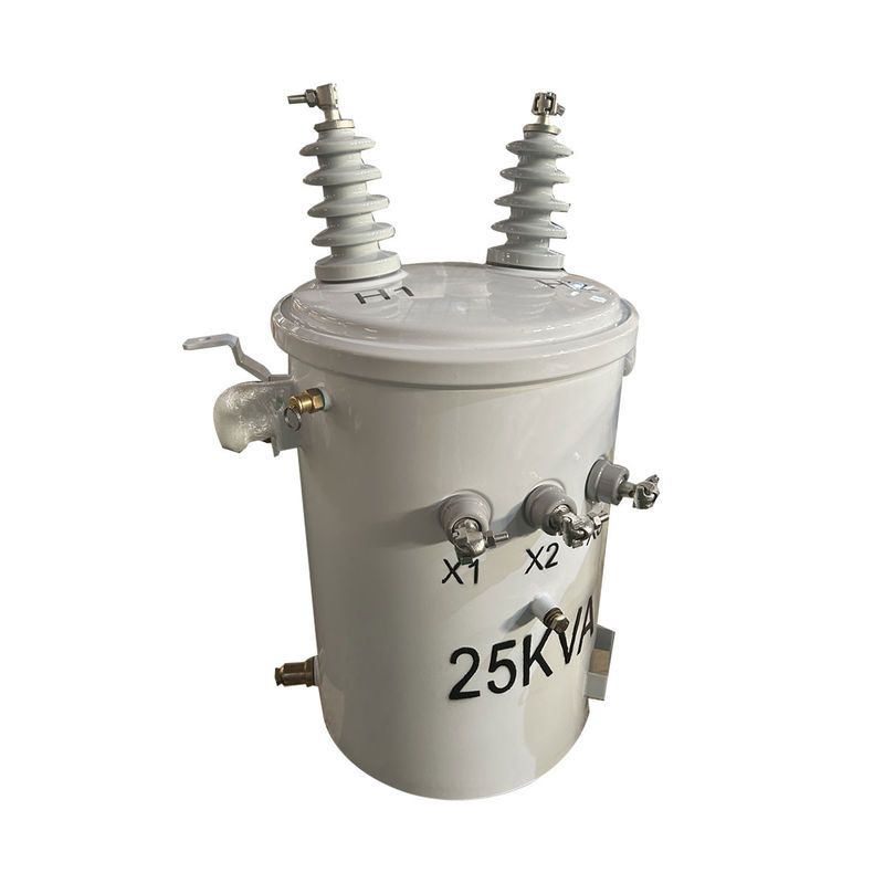
Oil-immersed transformers perform well inside industrial environments because insulating oil improves cooling efficiency and dielectric strength. Heat generated by electromagnetic induction transfers into the oil before dissipating through radiators or cooling fins. Stable operating temperatures reduce insulation aging and improve long-term reliability. Industrial facilities often experience fluctuating electrical loads, making effective cooling extremely important for operational stability. Oil insulation also protects internal windings from moisture contamination and electrical arcing. Many heavy-duty production systems require continuous operation for extended periods. Oil-immersed designs support those conditions effectively. Proper maintenance practices, including oil testing and thermal inspections, further improve transformer lifespan and operational safety across demanding manufacturing and commercial environments.