")
Solar Photovoltaic System-Solution
Industry Overview and Application Innovation
Integrated Solutions for PV Power Plants & C&I Distributed PV
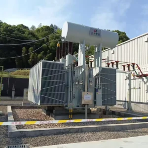
In PV power plants and commercial & industrial (C&I) distributed PV applications, Kerun Intelligent Control Co., Ltd. provides integrated power equipment and services covering the full chain of step-up grid connection — power distribution — protection & control — O&M support. Our core product portfolio includes PV substation main transformers / step-up transformers, prefabricated substations (box-type substations) (centralized European-type, distributed European-type, centralized American-type, distributed American-type), HV/LV switchgear assemblies (including RMUs, metal-clad switchgear, LV distribution panels, etc.), and new-energy supporting integrated solutions such as prefabricated cabins / battery energy storage cabins—all configurable and customizable to project voltage level, grid-connection scheme, and site installation conditions.
Case Study: Malaysia 80MW Project

Standards Compliance & Key Advantages
Kerun’s design and testing system strictly benchmarks major international and domestic standards (such as IEC 60076 / GB/T 1094 for transformer standards and IEC 62271 for switchgear standards), and we can implement environmental adaptation packages for high temperature, coastal salt mist, high altitude, and sandy/dusty conditions as required. Backed by years of experience in grid and new-energy projects, we deliver advantages including more accurate solution matching, tighter manufacturing process control, more consistent quality, and faster response—helping customers achieve higher grid-connection reliability, lower operational risk, and more predictable life-cycle cost.

From Factory Integration to Site Energization
To protect the project schedule in a PV site, the solution is built around factory integration rather than on-site assembly. The oil-immersed transformer is completed with strict checks on sealing, accessories, terminals, and safety details, then integrated with the SF6 RMU and the 0.8kV LV switchboard (4000A busbar) inside a 20ft containerized substation (Model YBW-6300(3150)/33(11)-0.8).
Once delivered, the unit is positioned on a prepared foundation, followed by MV/LV cable termination and earthing connection. With most wiring and functional verification completed before shipment, commissioning becomes faster and more predictable—focused on interlocks, insulation verification, and protection setting—supporting safe energization and quick grid connection under humid and tropical conditions such as Malaysia.


20ft Containerized Substation Solution
Model: YBW-6300 (3150) / 33 (11) – 0.8
Designed for fast deployment, high reliability, and low on-site workload—especially for PV plants and energy storage systems in humid and tropical environments.
A. Project & Supply Overview
| Item | Description | Remarks |
|---|---|---|
| Project | Malaysia Export – 80MW PV Power Plant + Energy Storage Project | PV application |
| Product | 20ft Containerized Substation (Prefabricated Substation) | Factory-integrated package solution |
| Quantity | 33kV system: 2 units; 11kV system: 2 units (Total 4 units) | Project supply scope |
| MV Switchgear | SF6 Gas-Insulated RMU (GIS RMU) | Compact, reliable, suitable for humid environments |
| Transformer Type | Oil-immersed Power Transformer | Engineered for long-term stable operation |
| LV Switchboard | 0.8kV, 4000A main busbar | Optimized for PCS busbar and high-current collection |
| Frequency / Phases | 50Hz / 3-phase | Configurable upon request |
| Delivery Concept | Factory-integrated, tested before shipment, plug-and-install at site | Less on-site work, faster commissioning |
What Makes This Solution “Project-Friendly”
Instead of shipping separate components and leaving complex integration to the site, we focus on factory pre-integration: MV RMU + transformer + LV switchboard + auxiliaries are assembled, wired, and function-checked in-house. This reduces:
-
On-site installation time
-
Construction and commissioning uncertainty
-
Coordination workload between multiple subcontractors
In short: we deliver certainty for your energization and grid-connection milestones.
B. Main Electrical Ratings (Per Unit)
| Parameter Item | Specifications | Remarks |
|---|---|---|
| MV Rated Voltage / Max System Voltage | 33kV / Um=36kV (33kV version); 11kV / Um=12kV (11kV version) | |
| LV Rated Voltage | 0.8kV (800Vac) | |
| Transformer Rated Power | 3150 kVA | Per unit |
| MV Rated Current | 55.1 A (33kV version); 165.3 A (11kV version) | Calculated at 3150kVA |
| LV Rated Current | 2273 A | Calculated at 3150kVA, 0.8kV |
| LV Main Busbar Rated Current | 4000 A (Copper busbar) | IEC 61439 temperature-rise design basis |
| Reference Power Capability of 0.8kV/4000A Busbar | Approx. 5.54 MVA | Engineering reference (actual depends on PF, derating, installation) |
Notes: Final short-circuit levels, protection settings, and feeder arrangement are confirmed by the single-line diagram (SLD) and grid requirements.
“Factory-Integrated” Means Real On-Site Savings
We don’t treat the factory as a production stop—we treat it as the first commissioning site. Before shipment, we verify:
-
Mechanical interlocking logic (MV)
-
LV functional checks and circuit continuity
-
Earthing integrity and bonding points
-
Ventilation / anti-condensation readiness
-
Labeling, terminal identification, and maintainability access
This approach is built for EPC reality: less rework, fewer surprises, faster energization.
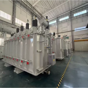
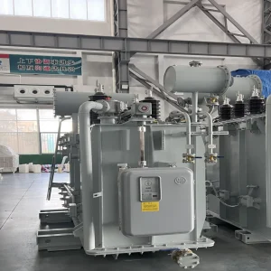
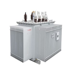
C. Oil-Immersed Transformer (Technical Data)
| Parameter Item | Specifications | Remarks |
|---|---|---|
| Type | Oil-immersed power transformer | Oil-immersed design for stable long-term operation |
| Rated Power | 3150 kVA | Typical rating for PV/BESS step-up/step-down application |
| Voltage Ratio | 33/0.8kV or 11/0.8kV | MV side depends on site grid level |
| Vector Group | Dyn11 | Common selection for PV/BESS integration |
| Cooling | ONAN (ONAF optional) | ONAF available if higher overload capacity is required |
| Impedance | 6.5% | Engineering-typical value; adjustable per system study |
| Tap Range / Method | ±2×2.5% (DETC, off-circuit) | Voltage adjustment during planned outage |
| Insulation Level (Typical) | Um 36kV: LI 170kVp / AC 70kV; Um 12kV: LI 75kVp / AC 28kV | Typical IEC insulation coordination levels |
| Temperature Rise (Typical) | Top oil ≤60K; winding ≤65K | Typical IEC limits for reliable thermal performance |
| Losses | As per IEC / project guaranteed limits | Guaranteed values to be stated in the final offer |
| Routine Tests | IEC 60076 routine tests + factory QA checklist | Full traceability with test reports before shipment |
| Standard Accessories | Oil temp / winding temp control, oil level indicator, PRD, sampling/drain valves, earthing points, etc. | Accessory list can be expanded per project requirements |
Built for Humid & Tropical Environments
In PV + BESS sites, moisture is a silent risk. Our design focuses on long-term stability through:
-
Anti-condensation heaters + ventilation strategy
-
Clear separation of MV / transformer / LV compartments
-
Robust sealing approach and cable entry treatment
-
Optional IP and anti-corrosion upgrades for coastal or high-humidity zones
We design not just for “passing tests,” but for stable operation after months and years on site.
D. MV Section – SF6 RMU
| Item | 33kV System (Um=36kV) | 11kV System (Um=12kV) |
|---|---|---|
| Switchgear Type | SF6 RMU | SF6 RMU |
| Rated Current (Busbar / LBS) | 630A | 630A |
| Short-Time Withstand | 25kA / 1s (typical utility grade) | 25kA / 1s (typical utility grade) |
| Insulation Level (Typical) | LI 170kVp / AC 70kV | LI 75kVp / AC 28kV |
| Typical Configuration | 2× Ring LBS + 1× Transformer Feeder (recommended VCB module) + optional metering/feeder | Same |
| Transformer Feeder Protection | VCB + numerical protection relay (recommended for 3150kVA) | Same |
| Gas Tank | Sealed SF6 tank with pressure indication / alarm (as configured) | Same |
| Interlocks & Safety | Earthing switch interlock, live-line indicator, anti-misoperation logic | Same |
Safety & Maintainability: Designed for Real Operators
We pay attention to what makes equipment truly “usable” on site:
-
Clear interlocks to prevent wrong switching sequences
-
Logical access and maintenance clearance inside compartments
-
Visible labels, terminal IDs, and functional markings
-
Earthing points and bonding straps placed where technicians actually need them
Good equipment is not only strong on paper—it is easy to operate correctly.
E. LV Section – 0.8kV PCS Busbar & Switchboard (4000A)
| Parameter Item | Specifications | Remarks |
|---|---|---|
| LV System Voltage | 0.8kV AC | Suitable for PCS busbar and LV distribution in PV+BESS applications |
| Main Busbar | 4000A Copper busbar (IEC 61439 temperature rise design) | Designed with sufficient thermal margin for continuous high-current operation |
| Incomer Breaker | ACB 4000A (motorized operation optional) | Flexible for local/remote operation; motorized option supports unmanned operation |
| Breaking Capacity (Recommended) | Icu/Ics ≥ 65kA (final by short-circuit calculation) | To be finalized based on system fault level and short-circuit study |
| Outgoing Feeders | MCCB/ACB feeders for PCS lines (quantity per project layout) | Feeder quantity and ratings configurable based on PCS capacity and system architecture |
| Metering | U/I/P/Q/PF/kWh; power quality / harmonics optional | Optional PQ monitoring helps improve system visibility and operational control |
| Protection Functions | Overcurrent / short-circuit / earth fault; EPO logic optional | EPO supports emergency shutdown scenarios for BESS safety management |
| Communication | Modbus RTU/TCP; IEC104 / IEC61850 gateway optional | Interface can be aligned with SCADA/EMS requirements and site communication protocol |

| Parameter Item | Specifications | Remarks |
|---|---|---|
| Container Type | 20ft Prefabricated Container Enclosure | Integrated MV RMU + Oil Transformer + LV Switchboard in one container |
| Compartment Layout | MV Compartment + Transformer Bay + LV Compartment | Clear functional separation for safety, inspection, and maintenance |
| Enclosure Protection | IP54 (Optional IP55) | Recommended for tropical & rainy environments |
| Anti-corrosion | C3 Standard (Optional C4) | Upgradable for coastal / salt-mist locations |
| Cable Entry | Bottom Entry with Sealing Plates / Gland System; Side Entry Optional | Sealed and engineering-friendly routing for faster site termination |
| Ventilation / Dehumidification | Forced Ventilation + Anti-condensation Heaters; A/C Optional | Reduce insulation risk caused by moisture/condensation |
| Lifting & Transport | Lifting Lugs / Skid Lifting Points; Sea-freight Reinforcement | Designed for safe handling and long-distance shipping |
| Earthing | Main Earthing Bar + Door Bonding + External Earthing Terminals | Reliable grounding continuity for operator safety and system protection |